SR Retention Flip-Flop/Latch :
- Lets have a look at a normal SR Flip Flop and Latch as below -
 Figure#1 : SR Flip-Flop
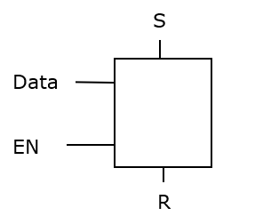
Figure#2 : SR Latch
- If these Flip-Flops/Latches needs to be retained during the power shut-down, these Flip-Flops/Latches circuits needs to be modified such that when the power restores, these Flip-Flops/Latches gets initialized to the previous value ( Value before power shut-down)
- Lets see the modified circuit diagrams of these cells which acts like a retention Flip-Flop/Latch

Figure#3 : Retention Flip-Flop
 Figure#4 : Retention Latch
 - As shown in figure#3 & #4, when the power is about to shut down , the 'Save' signal is asserted and the Flip-Flop/Latch output gets captured in the D-Latch (Which is powered and has the active power supply)
- Once the power is up, 'Restore' signal is asserted and the Flip-Flop/Latches gets initialized with the stored value in D-Latch
Hope, this article is helpful in understanding the basic concepts of Retention Flip-Flop/Latches and how they behave during power shut-down and power up.
------------------------------------------------------Happy Learning-------------------------------------
Comments
Post a Comment